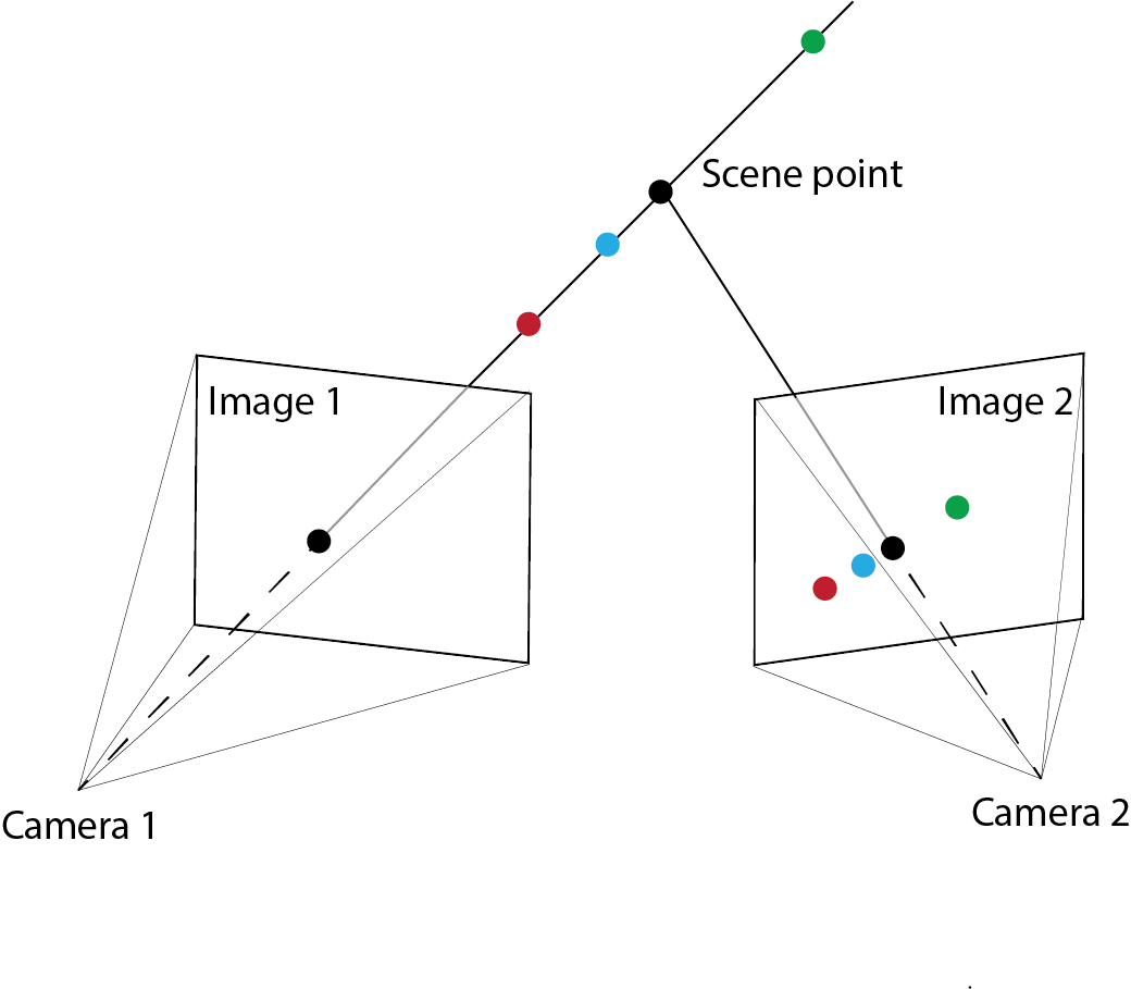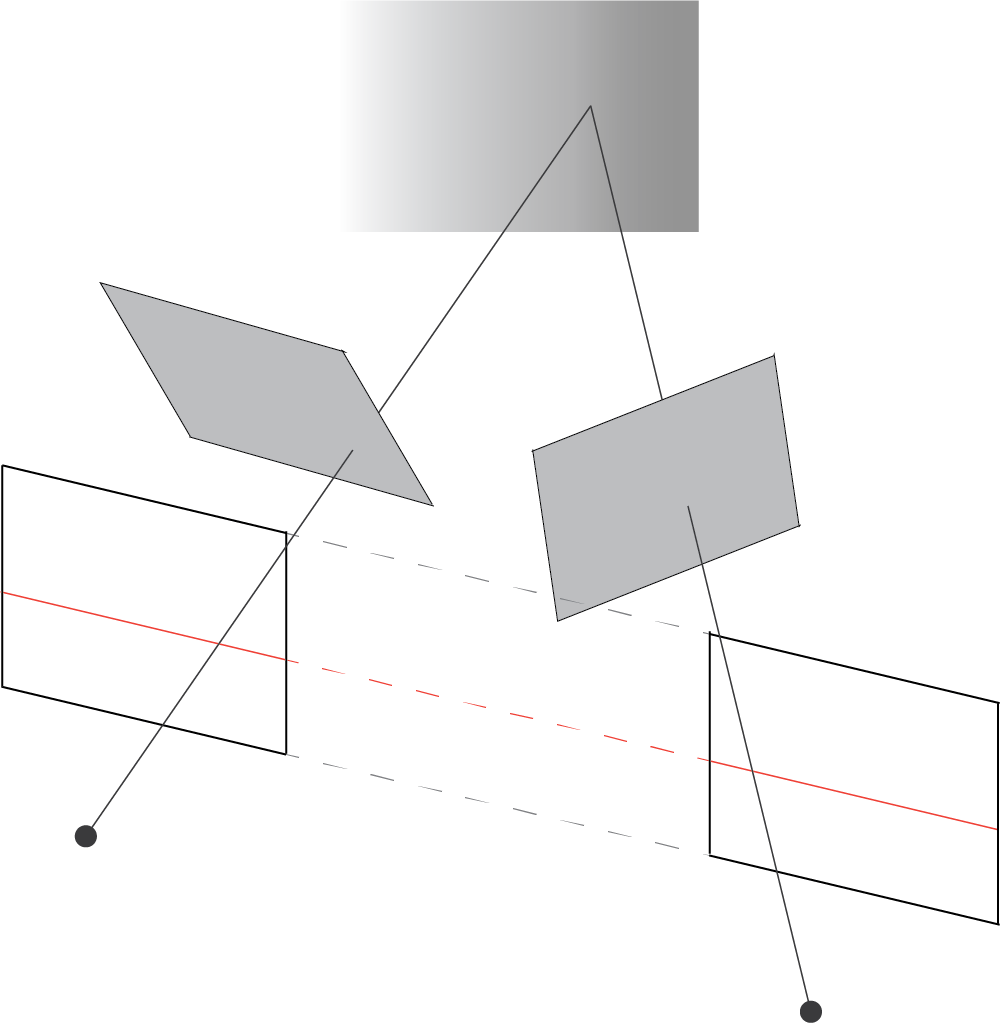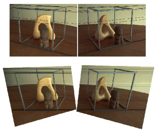
Epipolar Geometry
Faisal Qureshi
Professor
Faculty of Science
Ontario Tech University
Oshawa ON Canada
http://vclab.science.ontariotechu.ca
Copyright information
© Faisal Qureshi
License

This work is licensed under a Creative Commons Attribution-NonCommercial 4.0 International License.
Lesson Plan
- The need for multiple views
- Depth ambiguity
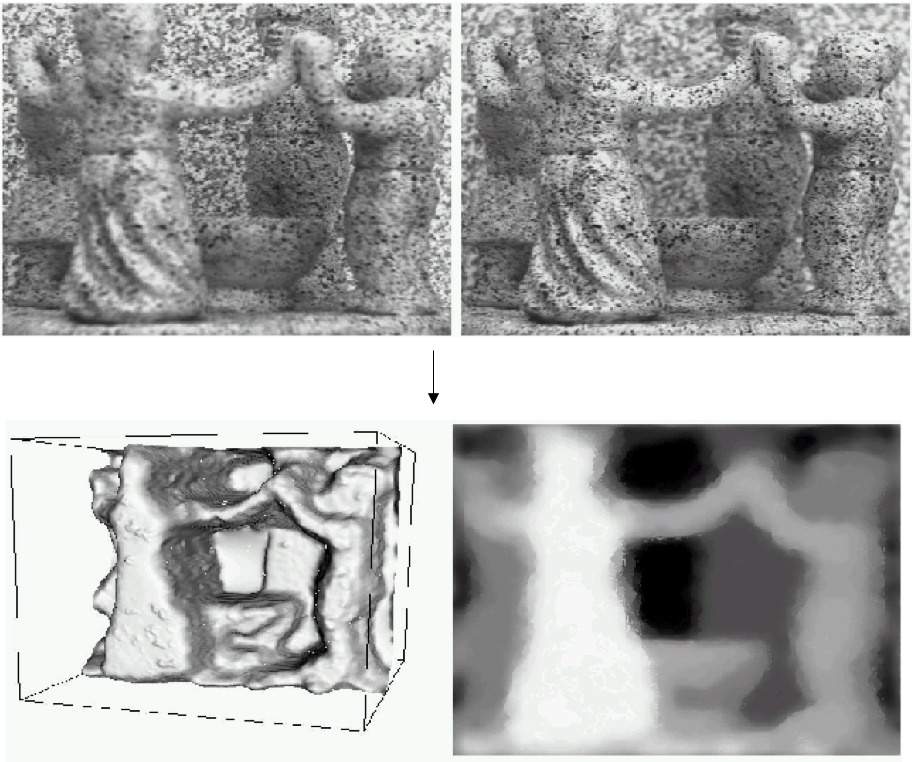
- Estimating scene shape
- Shape from shading
- Shape from defocus
- Shape from texture
- Shape from perspective cues
- SHape from motion
- Stereograms, human stereopsis, and disparity
- Imaging geometry for a simple stereo system
- Epipolar geometry
- Fundamental matrix
- Essential matrix
- Rectification
- Stereo matching
- Active stereo
The need for multiple views?
Structure and depth are inherently ambiguous from single views.
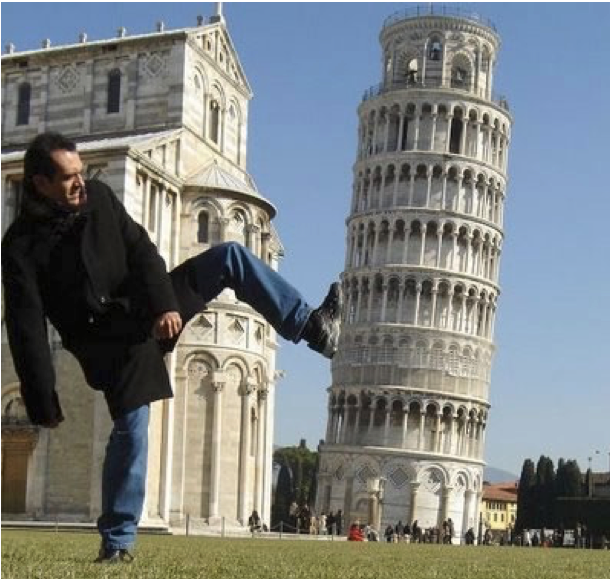
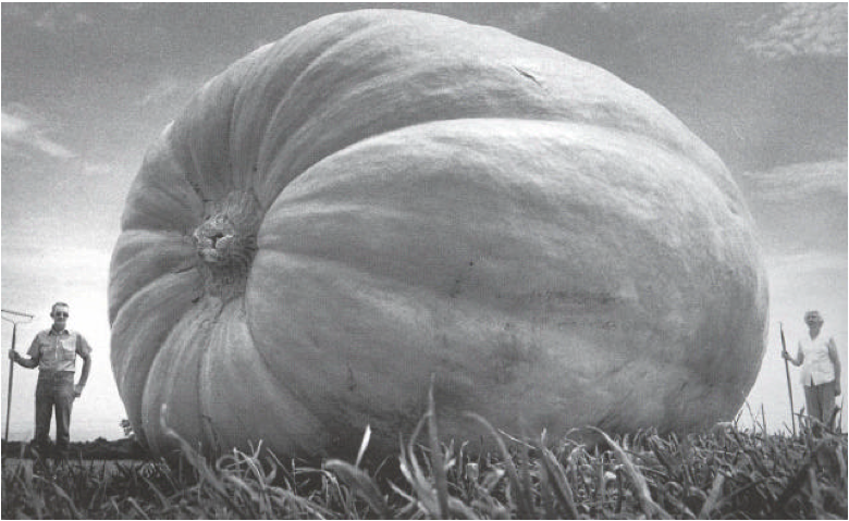
Figures from Lana Lazebnik.
Depth ambiguitiy
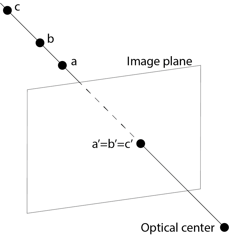
Notice that 3D points $a$, $b$, $c$ all project to the same location $a'=b'=c'$ in the image. This suggests that there is no straightforward scheme of estimating the depth given an image.
Estimating scene shape
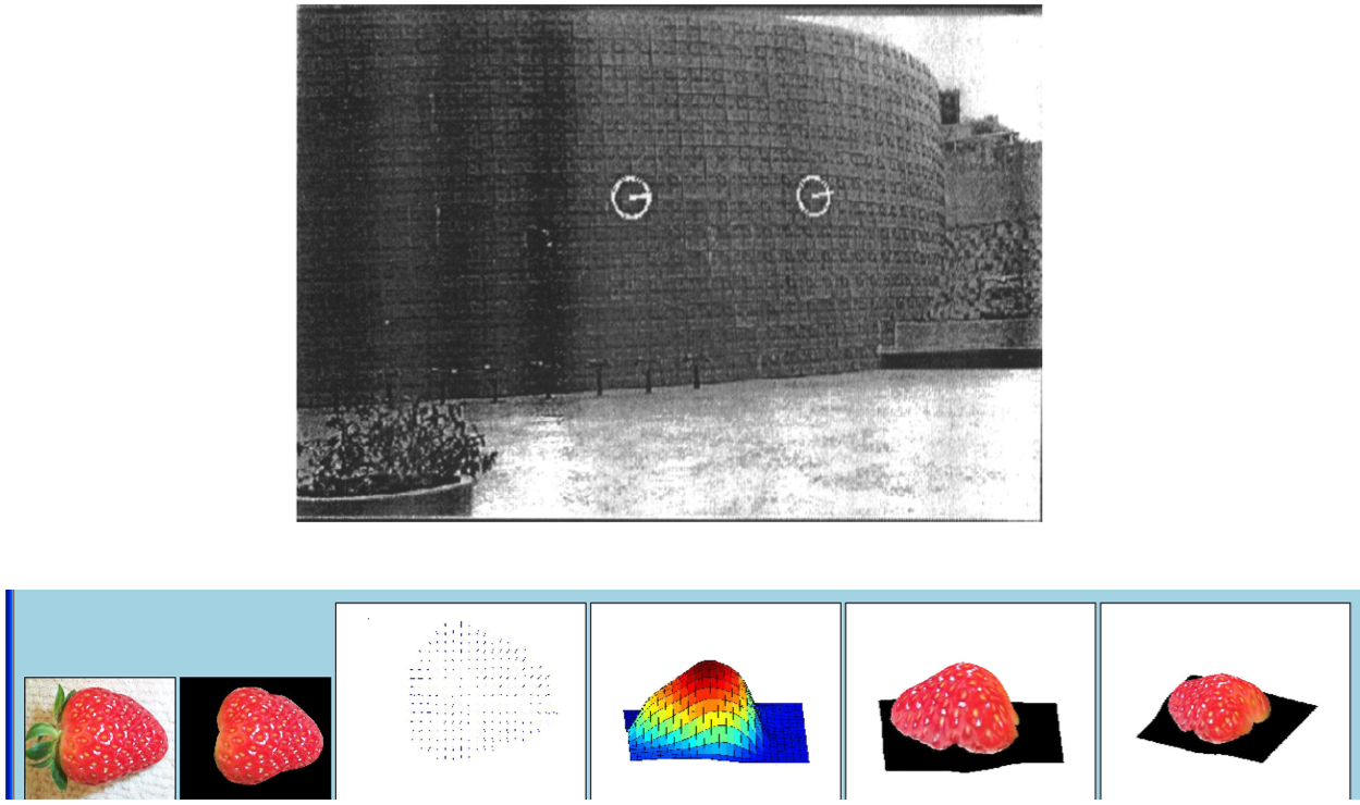
- "Shape from X", where X is one of shading, texture, focus, or motion.
Shape from shading

Shape from defocus
Shape from texture
Shape using perspective cues

Human eye
- Pupil/iris: control the amount of light passing reaching the retina
- Retina: contains photo-sensitive cells, where image is formed
- Fovea: highest concentration of cones
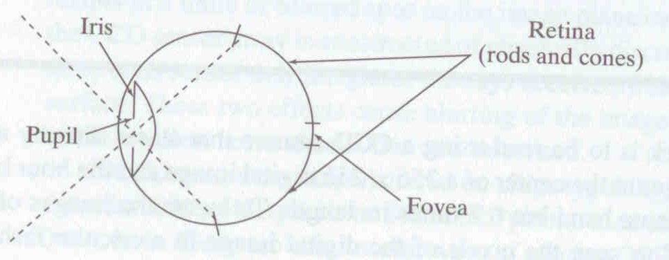
Human stereopsis: disparity
Human eyes fixate on points in space--rotate so that corresponding images form in the centers of fovea
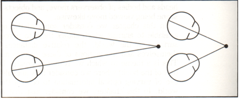
From Bruce and Green, Visual Perception, Physiology, Psychology and Ecology
Disparity occurs when eyes fixate on one object; others appear at different visual angles
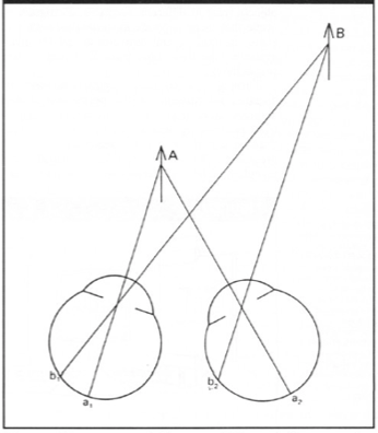
From Bruce and Green, Visual Perception, Physiology, Psychology and Ecology
Specifically, disparity $d$ is given by the following relation
$$ d = r - l = D - F $$
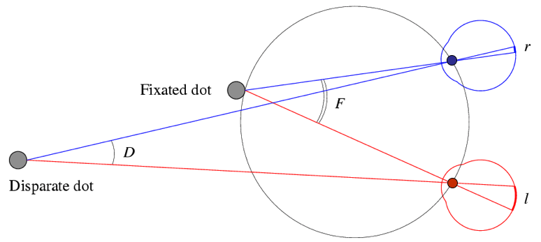
Forsyth and Ponce
Random dot stereograms
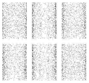
- Julesz 1960: Do we identify local brightness patterns before fusion (monocular process) or after (binocular)?
- Pair of synthetic images obtained by randomly spraying black dots on white objects
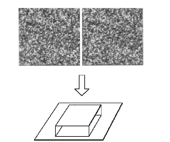
- Findings: when viewed monocularly, they appear random; when viewed stereoscopically, see 3d structure.
Conclusion
- Human binocular fusion not directly associated with the physical retinas; must involve the central nervous system
- Imaginary “cyclopean retina” that combines the left and right image stimuli as a single unit
Stereo photography and stereo viewers
Take two pictures of the same subject from two slightly different viewpoints and display so that each eye sees only one of the images.
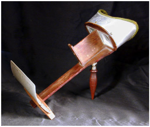
Invented by Sir Charles Weatstone, 1838.
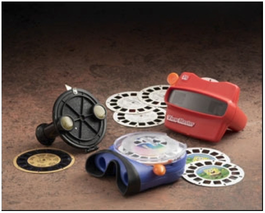
Image from fisher-price.com
3D cinema
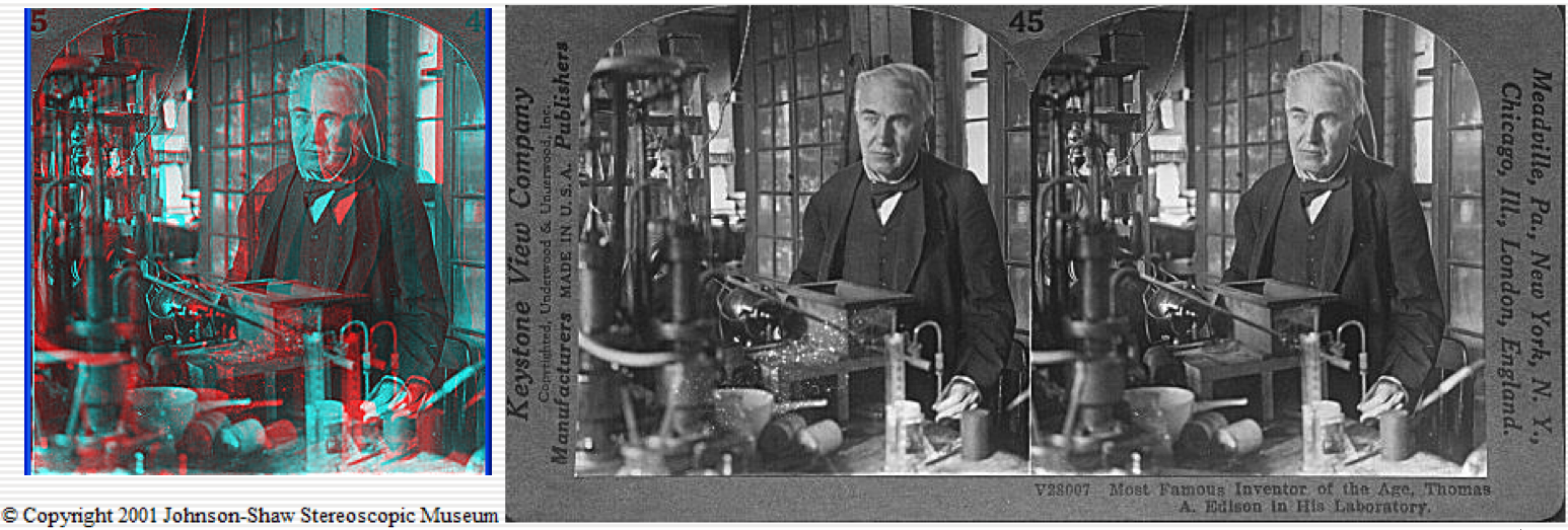
http://www.johnsonshawmuseum.org
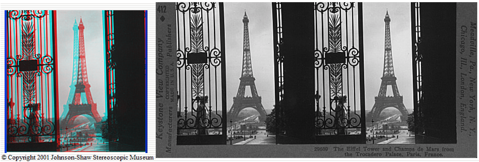
http://www.johnsonshawmuseum.org

http://www.johnsonshawmuseum.org
Stereo glasses needed to watch 3D movies.

http://www.johnsonshawmuseum.org
Brain fuses information from left/right images when these are shown in quick succession to give an appearance of depth.

http://www.well.com/~jimg/stereo/stereo_list.html
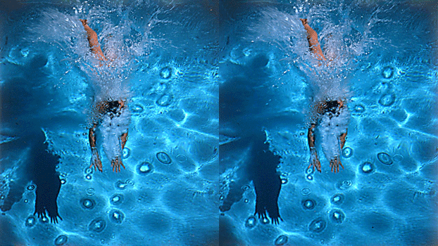
http://www.well.com/~jimg/stereo/stereo_list.html
Autostereograms
- Exploit disparity as depth cue using single image.
- Sometimes referred to as single image random dot stereogram or single image stereogram
Seeing 3D structure
Try to see beyond the image, merging the two dots in the process. You should percieve a 3D structure. See if you can see it.
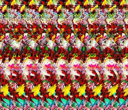
magiceye.com
If it works out, you will see the following 3D structure.
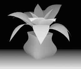
magiceye.com
Estimating depth with stereo
- Shape from "motion" between two views
- Infer 3D shape of scene from two (multiple) images from different viewpoints
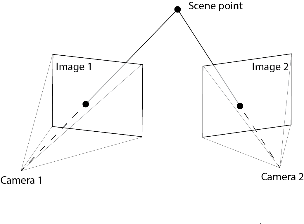
Find the same point in two images (local feature descriptors?)

Imaging geometry
- Extrinsic params
- Rotation matrix and translation vector
- Intrinsic params
- Focal length, pixel sizes (mm), image center point, radial distortion
We’ll assume for now that these parameters are given and fixed.
Here extrinsic parameters describe the relationship between two cameras or a single moving camera.
Geometry for a simple stereo system
Assuming parallel optical axes and known camera parameters (i.e., calibrated cameras), we get the following setup:
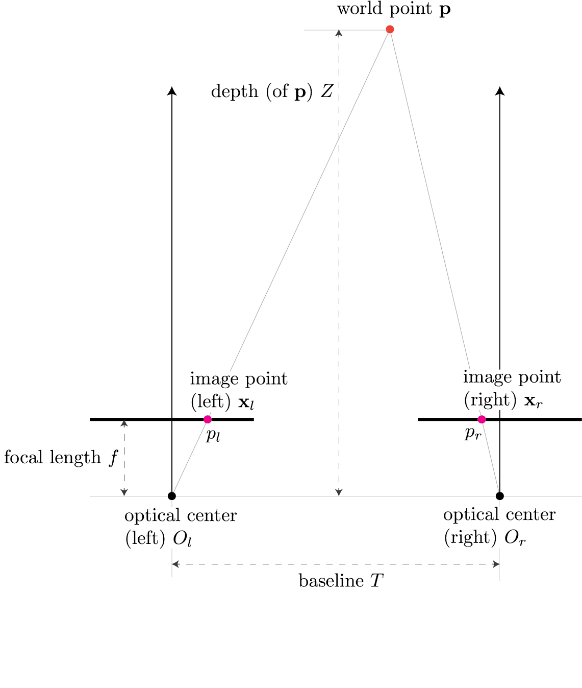
Consider $\triangle (p_l, \mathbf{p}, p_r)$ shown in red and $\triangle (O_l, \mathbf{p}, O_r)$ shown in blue in the following figure
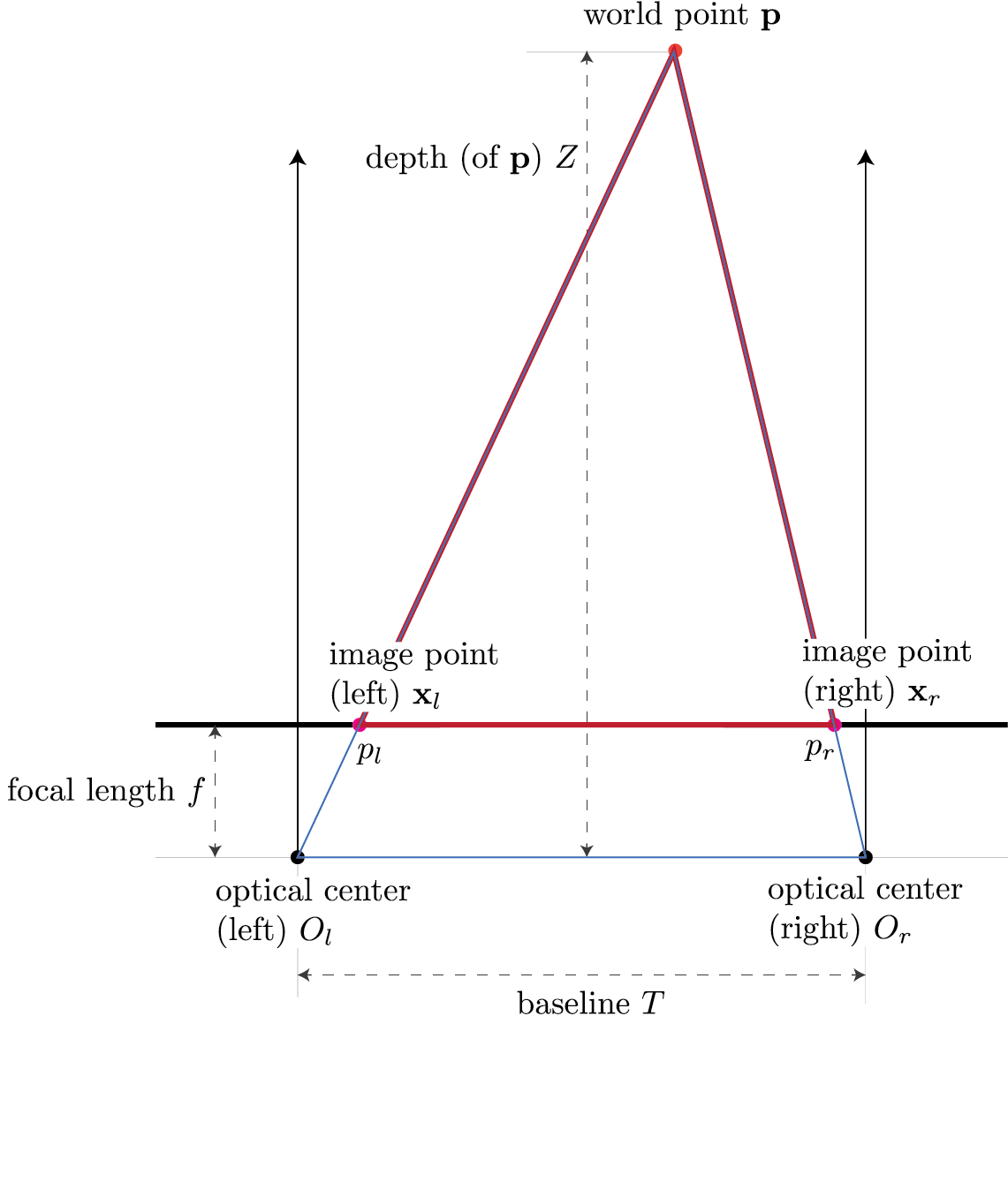
Use pinhole model to map world point $\mathbf{p}$ to image point $\mathbf{x}_l$ in the left camera:
$$ \mathbf{x}_l = f \frac{X}{Z}. $$
Now, use pinhole model to map world point $\mathbf{p}$ to image point $\mathbf{x}_r$ in the right camera:
$$ \mathbf{x}_r = f \frac{X-T}{Z}. $$
Here we employ the fact that if the world point $\mathbf{p}$ is $(X,Z)$ in the left camera then the same world point will be $(X-T,Z)$ in the right camera because the right camera is shifted by $T$.
We define disparity as $$ d = \mathbf{x}_l - \mathbf{x}_r. $$
This gives us
$$ \begin{align} d &= \mathbf{x}_l - \mathbf{x}_r \\ &= f \frac{X}{Z} - f \frac{X-T}{Z} \\ &= \frac{fX - fX + fT}{Z} \\ &= f \frac{T}{Z} \end{align} $$
This suggests that we are able to estimate the depth of point $\mathbf{p}$ by using disparity $(\mathbf{x}_l - \mathbf{x}_r)$:
$$ Z = f \frac{T}{d} $$
Depth from disparity
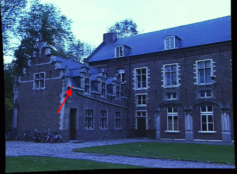
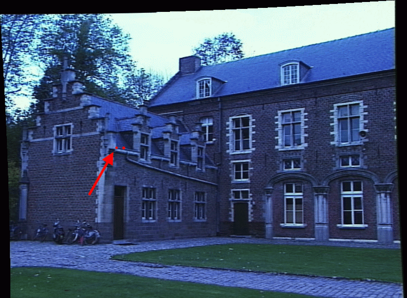
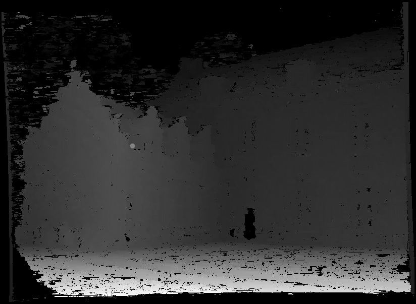
If we can find corresponding points (locations) in two images (top and middle), we can compute disparity for these locations (last row). We can then use disparity to calculate the relative depth.
- Top figure
- Red dot with arrow is $(x,y)$
- Middle figure
- Red dot with arrow is $(x',y')$
- Bottom figure
- Red dot disparity $D(x,y)$ for location $(x,y)$ in top image
Then
$$ (x',y') = (x + d(x,y), y) $$
Aside: the red dot without arrows in top figure is $(x',y')$ and the red dot without arrows in bottom figure is $(x,y)$. This confirms that the same 3D point appears at different locations in the two images.
Depth from stereo: key idea
Triangulate from corresponding image points in two or more images.
Stereo matching
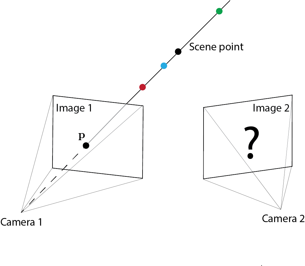
- Given a point in one image (say left image below), where do we find the corresponding point in the second image (say right image below)?
Epipolar geometry
- Epipolar geometry is defined by two cameras. Given an image location in one camera, the epipolar constrat identifies the location(s) in the other camera that must contain the corresponding image point.
- If extrinsic parameters are available for both cameras, the epipolar constraints is often used to speed up correspondence search (stereo matching).
Epipolar constraint
Given an image point $p$ in the left image, its correspondence points in the right image must lie on the line $\overline{e'p'}$. Note that this line is the intersection of two planes: 1) right image plane and plane $oo'p$. Plane $oo'p$ is contains the point $p$ in the left image and the two optical centers.
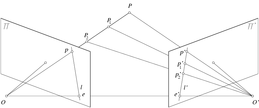
Figure from Hartley and Zisserman
Definitions
Figure from Hartley and Zisserman
- Baseline: line joining optical centers - $\overline{oo'}$
- Epipole: image plane/baseline intersection location - $e$ and $e'$
- Epipolar plane: plane containing $oo'P$.
- Epipolar line: intersection of epipolar plane and image plane - line $l$ in the right image and line $l'$ in the left image
- All epipolar lines pass through epipole point
Example
Corresponding epipolar lines drawn in the left and the right images.
Figure from Hartley and Zisserman
Epipolar lines: converging cameras
Figure from Hartley and Zisserman
Epipolar lines: parallel cameras
- Where are the epipoles in the two images?
- Infinity
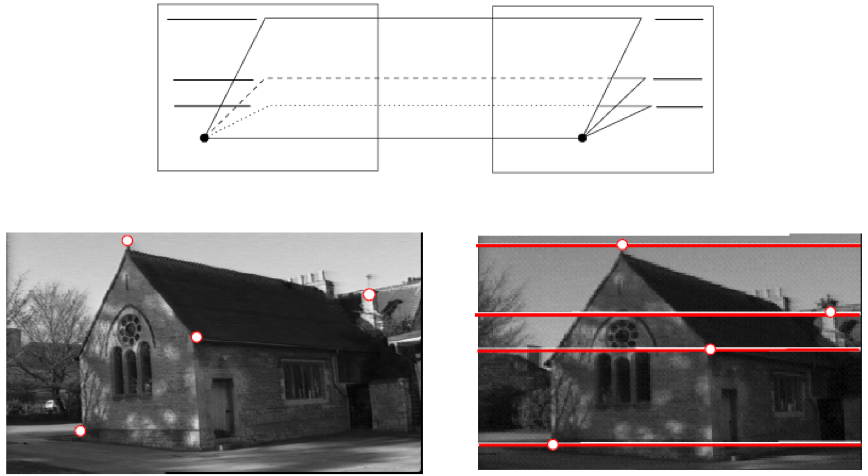
Figure from Hartley and Zisserman
Epipolar lines: forward motion
- Epipole has same coordinates in both images: $e = e'$.
- Points move along lines radiating from epipole $e$: "focus of expansion"
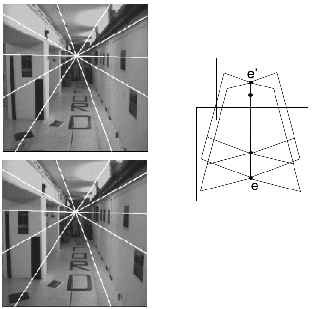
Figure from Hartley and Zisserman
Epipolar constraint for stereo matching
Using the epipolar constraint reduces stereo matching to "search in 1D" problem.

Figure from Hartley and Zisserman
Fundamental matrix
Fundamental matrix is algebraic representation of epipolar geometry.
Consider the following setup. For a point $\mathbf{x}$ in image $I$ there exists an epipolar line $\mathbf{l}'$ in image $I'$. Any point $\mathbf{x}'$ in image $I'$ matching point $\mathbf{x}$ must sit on this line $\mathbf{l}'$.
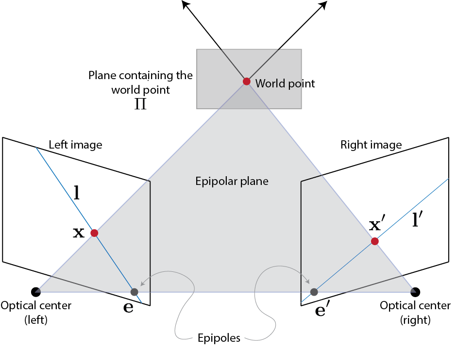
Let us a consider a plane $\Pi$ that doesn't pass through either camera centers. A ray through the first camera center passing through point $\mathbf{x}$ meets plane $\Pi$ at point $\mathbf{X}$. Point $\mathbf{X}$ is then projected on image 2 at point $\mathbf{x}'$. $\mathbf{x}'$ has to lie on epipolar line $\mathbf{l}'$. Points $\mathbf{x}$ and $\mathbf{x}'$ are projectively equivalent to $\mathbf{X}$, because points $\mathbf{x}$ and $\mathbf{x}'$ are images of 3D point $\mathbf{X}$ lying on a plane. This means that points $\mathbf{x}$ and $\mathbf{x}'$ are related via a homography $H_{\Pi}$. We assume that $\mathbf{X}$ lies on a plane simply for mathematical convenience. The above discussion holds in general.
Thus
$$ \mathbf{x}' = H_{\Pi} \mathbf{x} $$
Epipolar line corresponding to point $\mathbf{x}$ passes through epipole $\mathbf{e}'$ and point $\mathbf{x'}$. Therefore,
$$ \begin{align} \mathbf{l}' &= \mathbf{e}' \times \mathbf{x}' \\ &=[\mathbf{e}']_{\times} \mathbf{x}' \\ &= [\mathbf{e}']_{\times} H_{\Pi} \mathbf{x} \\ &= F \mathbf{x} \end{align} $$
Here $F = [\mathbf{e}']_{\times} H_{\Pi}$ is the fundamental matrix. $[\mathbf{e}']_{\times}$ has rank 2 and $H_{\Pi}$ has rank 3; therefore, $F$ has rank 2. $F$ represents a mapping from 2-dimensional onto a 1-dimensional projective space.
Algebraic derivation of fundamental matrix F
Consider a camera matrix $P$. The ray backprojected from $\mathbf{x}$ by $P$ is obtained by solving $P \mathbf{X} = \mathbf{x}$:
$$ \mathbf{X}(\lambda) = P^+ \mathbf{x} + \lambda \mathbf{C} $$
Here $P^+$ is the pseudo inverse of $P$, such that $PP^+ = \mathbf{I}$. $\mathbf{C}$ is the camera center obtained using $P \mathbf{C}=$ ($\mathbf{C}$ is null-vector of $P$.)
Two points on line above are $P^+ \mathbf{x}$ when $\lambda=0$ and $\mathbf{C}$ when $\lambda=\infty$. These two points are imaged by the second camera $P'$ at $P'P^+\mathbf{x}$ and $P'\mathbf{C}$. Note that $P'\mathbf{C}$ is epipole $\mathbf{e}'$.
The epipolar line is
$$ \begin{align} \mathbf{l}' &= (P' \mathbf{C}) \times (P' P^+ \mathbf{x}) \\ &= [\mathbf{e}']_{\times} P'P^+ \mathbf{x} \\ & = F \mathbf{x} \end{align} $$
This is essentially the same formulation. Here $H_{\Pi} = P'P^+$.
Fundamental matrix relationship
Note that point $\mathbf{x}'$ lies on epipolar line $l'$. Therefore, the following must be true:
$$ \begin{align} &\ {\mathbf{x}'}^T \mathbf{l}' &= 0 \\ \Rightarrow &\ {\mathbf{x}'}^T F \mathbf{x} &= 0 \end{align} $$
Observations
- This relationship provides a mechanism for characterizing the fundamental matrix $F$ without reference to camera matrix.
- It is possible to compute $F$ given point correspondences between two images.
- If ${\mathbf{x}'}^T F \mathbf{x}=0$ holds then points $\mathbf{x}$ and $\mathbf{x}'$ are co-planar.
Properties of fundamental matrix
- Transpose: if $F$ is the fundamental matrix for camera paper $(P,P')$ then $F^T$ is the fundamental matrix of pair $(P',P)$.
- Epipolar lines: for any point $\mathbf{x}$, the corresponding epipolar line is $\mathbf{l}'=F \mathbf{x}$. Similarly, for point the $\mathbf{x}'$, the corresponding epipolar line is $\mathbf{l}=F^T \mathbf{x}'$.
- Epipoles: $\mathbf{e}'$ is the left null-vector of $F$. Similarly, $\mathbf{e}$ is the right null-vector of $F$.
Essential matrix
- The matrix $F$ is referred to as the essential matrix when image intrinsic parameters are known.
- More generally the matrix $F$ is referred to as the fundamental matrix
- The uncalibrated case
Eight-point algorithm for estimating the fundamental matrix
The fundamental matrix $F$ is a 3-by-3 matrix:
$$ F = \left[ \begin{array}{ccc} f_{11} & f_{12} & f_{13} \\ f_{21} & f_{22} & f_{23} \\ f_{31} & f_{32} & f_{33} \\ \end{array} \right]. $$
It can be determined up to an arbitrary scale factor, i.e., this matrix has 8 unknowns. Consequently, we need eight equations to estimate this matrix. Given points $\mathbf{x}=(x,y,1)$ and $\mathbf{x}'=(x',y',1)$, we know that
$$ \mathbf{x}' F \mathbf{x} = 0. $$
We can re-write the above equation as follows:
$$ \left[ \begin{array}{ccccccccc} xx' & yx' & x' & xy' & yy' & y' & x & y & 1 \end{array} \right] \left[ \begin{array}{c} f_{11} \\ f_{12} \\ f_{13} \\ f_{21} \\ f_{22} \\ f_{23} \\ f_{31} \\ f_{32} \\ f_{33} \end{array} \right] = 0 $$
If we have eight points, we can stack 8 such equations and set up the following system of linear equations
$$ \mathbf{A} \mathbf{f} = 0. $$
We can solve it by applying Singular Value Decomposition to $\mathbf{A}$. SVD of $\mathbf{A}$ yields $\mathbf{U} \mathbf{S} \mathbf{V}^T$. The solution is the last column of $\mathbf{V}$.
Recall that the fundamental matrix is a rank 2 matrix. The above estimation procedure doesn't account for that. For a more accurate solution, find $\mathbf{F}$ as the closest rank 2 approximation of $\mathbf{f}$.
Stereo matching: finding corresponding points
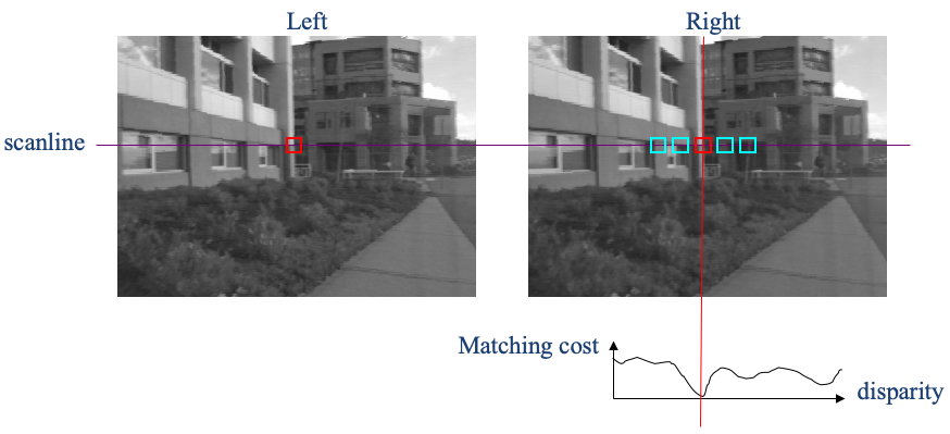
Epipolar geometry constraints our search, but the stereo matching problem isn't full solved yet. Consider the following rectified image pair. Our goal is to find the pixel/region in the right image that matches the pixel/region highlighted in the left image.
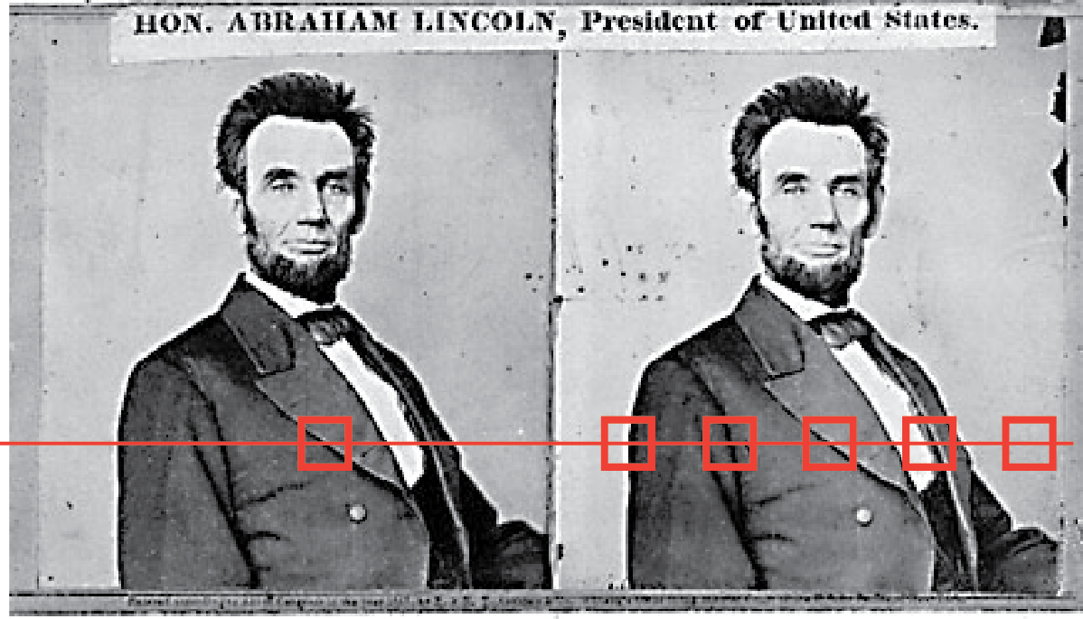
General idea
- For each pixel $\mathbf{x}$ in the left image
- Find the corresponding epipolar line (or scan line if the image pair is rectified) in the right image
- Examine all pixels in the scanline and pick the best match $\mathbf{x}'$
- Compute disparity $\mathrm{disp}=|\mathbf{x} - \mathbf{x}'|$ and use it to estimate depth $d(\mathbf{x}) = \frac{f b}{\mathrm{disp}}$, where $f$ is the focal length and $b$ is the baseline.
Matching
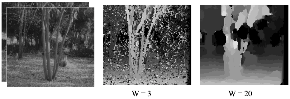
It is often better to match regions, rather than pixel intensities.
The size of the window used for matching effects the overall performance. Smaller windows create more detailed depth maps, but also lead to higher noise. Larger windows result in smoother disparity maps, but these lack fine details.
Matching continues to be a difficult problem, especially when dealing with texture-less surfaces, occlusions, repetitions, non-lambartian surfaces, surfaces exhibiting specularities, or transparencies. Often the following three priors are employed to improve matching.
- Uniqueness: for a point in one image there should be at most one match in the second image
- Ordering: corresponding points should be in the same order in two images. Note that this condition doesn't hold when dealing with occlusions.
- Smoothness: world is mostly composed of "flatt-ish" objects, so disparity values shouldn't change drastically from pixel to pixel. This condition too doesn't always hold
Active stereo
- Use "structured" light pattern to simply the correspondence problem
- Requires a single camera

From Rapid Shape Acquisition Using Color Structured Light and Multi-pass Dynamic Programming, Zhang, Curless, and Seitz
Microsoft Kinect Cameras
- Structured infrared light
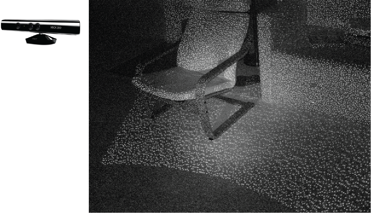
From https://bbzippo.wordpress.com/2010/11/28/kinect-in-infrared/
Summary
- Depth from stereo: main idea is to triangulate from corresponding image points.
- Epipolar geometry defined by two cameras
- We’ve assumed known extrinsic parameters relating their poses
- Epipolar constraint limits where points from one view will be imaged in the other
- Makes search for correspondences quicker i.e., speeds up stereo matching
Important terms
- epipole
- epipolar plane/lines
- disparity
- rectification
- intrinsic/extrinsic parameters
- essential and fundamental matrices
- baseline
- matching problem
- priors
- active stereo
- structured light
Expressing cross-product as matrix-vector product
Given
$$ \mathbf{a}=[a_1, a_2, a_3] $$
and
$$ \mathbf{b}=[b_1, b_2, b_3] $$
Define
$$ [\mathbf{a}]_{\times}= \left[ \begin{array}{ccc} 0 & -a_3 & a_2 \\ a_3 & 0 & -a_1 \\ -a_2 & a_1 & 0 \\ \end{array}\right] $$
Then
$$ \mathbf{a} \times \mathbf{b} = [\mathbf{a}]_{\times} \mathbf{b} $$

